Gas Solenoid Valve: Overview, Types, Function
Gas solenoid valves serve as essential components in controlling gas flow across industrial and residential applications. These devices ensure safe and precise control of gases like natural gas and propane through electromagnetic operation.
From water treatment plants to household gas appliances, solenoid valves maintain reliable flow control and safety standards.
The operation of these valves centers on electromagnetic mechanisms that manage gas flow paths effectively. Each valve opens, closes, and regulates flow rates based on specific application needs.
Multiple configurations, including 2-port, 3-port, and 4-port designs, allow these valves to handle varied flow requirements in different systems.
This article details the main types of solenoid valves, their key components, and operating principles. Read on to learn about essential safety features and practical applications across industrial and residential settings.
Understanding these valves helps ensure proper selection and implementation for safe gas flow control.
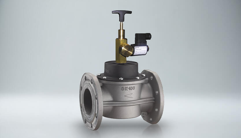
What is a gas solenoid valve?
A gas solenoid valve is an electrically controlled valve used to regulate or shut off gas flow in industrial, commercial, and safety systems.
How Does A Solenoid Valve Work?
Gas solenoid valves operate through electromagnetic induction principles. The solenoid coil generates a magnetic field when voltage passes through it, creating mechanical force. This force moves a ferromagnetic plunger positioned at the coil’s center in a linear motion.
A precise mechanical linkage allows the plunger to control valve operations. The magnetic field’s strength relies on the coil’s loop count and current flow. When the magnetic field dissipates, a spring mechanism returns the plunger to its starting position.
Response times vary between valve types. Direct-acting solenoid valves complete operations within 5 to 10 milliseconds. Pilot-operated versions need 15 to 150 milliseconds, based on their size.
These differences occur because direct-acting valves use electromagnetic force alone, while pilot-operated types utilize gas pressure to assist valve movement.
Application requirements determine power needs, primarily based on fluid pressure and orifice dimensions. DC systems typically operate between 6 and 240 volts, while AC applications use 24 to 480 volts at 60Hz.
These specifications enable precise control of gas flow, direction, and pressure during operation.
Some applications demand finer control capabilities. Proportional solenoid valves use pulse width modulation (PWM) for these situations.
This method achieves stable intermediate positions by alternating between energized and de-energized states. Adjusting duty cycles allows exact control over gas flow rates.
Gas Solenoid Valve Core Components
Gas solenoid valves rely on three essential components working together to ensure reliable performance and effective gas flow control. Each component plays a specific role in valve operation.
Electromagnetic Coil Assembly
The electromagnetic coil serves as the central element of the solenoid system. Numerous turns of enameled copper wire wrap around a cylindrical core to form this vital component. When energized, the assembly produces a magnetic field that drives valve operation. An epoxy encapsulation and iron frame surround the coil, minimizing magnetic path resistance.
Valve Body Construction
The valve body provides housing for internal components and establishes the gas flow framework. Material options from manufacturers include:
- Brass and stainless steel for corrosion resistance
- Aluminum for lightweight applications
- PVC for specific chemical compatibility
The body features inlet and outlet ports connecting to the gas circuit. Proper gas medium compatibility and operational integrity depend on the body’s construction and sealing capabilities.
Plunger and Spring Mechanism
The plunger-spring assembly functions as the main moving component. Constructed from ferromagnetic material, the plunger responds to the coil’s electromagnetic field.
A precision spring maintains proper plunger positioning – pushing downward in normally closed valves or upward in normally open designs.
An armature tube guides the plunger’s movement. The plunger’s attached seal creates tight closure against the orifice, enabling precise gas flow control. Manufacturers choose 430 F stainless steel for plungers and 302 stainless steel for springs, ensuring lasting durability.
Solenoid Valve Types
Gas solenoid valves feature distinct classifications based on operational states and actuation methods. The selection of appropriate valve types ensures optimal performance in specific gas control applications.
Normally closed solenoid valve
Normally closed valves block gas flow when de-energized, maintaining a sealed position. The electromagnetic field lifts the plunger during energization, creating a gas flow passage. Industrial furnaces and boilers commonly use this configuration where safety and containment remain critical.
Normally open solenoid valve
Unlike their closed counterparts, normally open valves allow gas flow in de-energized states. Energization moves the plunger downward, sealing the valve and stopping flow. These valves prove essential in systems needing continuous flow during power interruptions.
Bi-stable solenoid valve
Bi-stable valves differ from standard designs by maintaining position without constant power. Permanent magnets replace springs in these valves, with state changes occurring through brief power pulses. This design reduces power consumption for extended operation periods.
Direct Acting vs Pilot Operation
Direct-acting valves offer quick response, completing operations within 5-10 milliseconds through plunger movement. Pilot-operated systems need 0.5 bar minimum pressure differential, utilizing system pressure for control force amplification. Smaller solenoids manage higher flow rates through this design approach.
Normally Open vs Normally Closed States
Application requirements determine the choice between normally open and closed states. Systems needing frequent cycling benefit from normally closed valves. Applications requiring extended continuous flow work better with normally open configurations. Gas alarm systems utilize normally open valves with manual opening features for enhanced safety.
Circuit Functions of Solenoid Valves
Circuit functions establish how solenoid valves control gas flow through various ports and positions. These fundamental operations determine the valve’s role in gas control systems.
2-way solenoid valve
2-way solenoid valves provide basic gas flow control through one inlet and one outlet port. The operation mirrors single-pole single-throw electrical switches, managing a single flow path. Flow direction arrows on the valve body guide proper installation and operation.
Normally closed 2-way configurations seal the plunger against the orifice during power-off states, preventing gas flow. The plunger rises when energized, creating a flow path from cavity port through body orifice port. Normally open designs utilize spring force to push the plunger upward, sustaining flow until energized.
3-way solenoid valve
3-way solenoid valves feature three essential ports:
- Inlet (pressure port)
- Outlet (actuator port)
- Exhaust port (return port)
These valves manage pressure application and exhaust in downstream equipment. Two ports maintain open positions at any time, with configurations changing based on valve energization.
During de-energized states in normally closed 3-way valves, the outlet connects to exhaust while blocking inlet flow. Energization opens the inlet to outlet connection while closing the exhaust port.
The 3-way configuration enables precise gas distribution and mixing control. This design proves particularly effective for pneumatic control systems by combining pressure application and relief functions in one unit.
Operating Principles of Gas Solenoid Valves
Gas solenoid valves rely on precise interactions between electromagnetic and mechanical forces. The valve’s coil produces a magnetic field upon receiving electrical signals, pulling the plunger against spring action. This magnetic force must overcome both spring force and gas medium pressure forces.
Valve characteristics depend heavily on actuation methods. Direct-acting valves complete operations within 5-10 milliseconds. Pilot-operated versions need 15-150 milliseconds, varying with size. These timing differences result from unique operational mechanisms.
Pilot-operated systems utilize differential fluid pressure for valve operation. The system requires a 0.5 bar minimum pressure differential to amplify control forces. The pilot valve closure allows pressure buildup on both diaphragm sides through a bleed orifice.
Opening the pilot valve then releases upper diaphragm pressure, enabling bottom pressure to raise the diaphragm.
Operational capabilities extend beyond simple open-close functions. Pulse width modulation enables precise position control through electrical signal variation. This feature allows exact gas flow regulation across industrial and residential applications.
Semi-direct acting valves enhance reliability by combining direct and indirect mechanisms. These valves function effectively from zero bar pressure.
The plunger-membrane direct connection opens both the main valve and secondary orifice during activation, creating pressure drop and membrane elevation.
Safety Features in Gas Solenoid Systems
Gas solenoid valve systems incorporate essential safety mechanisms to protect equipment and personnel. These features provide critical defense against potential hazards across applications.
Emergency Shutdown Mechanisms
Emergency gas shutdown systems ensure immediate gas supply isolation during critical events. UL-listed gas solenoid valves stop flow instantly upon activation. The system maintains gas supply interruption by de-energizing connected devices until emergency resolution.
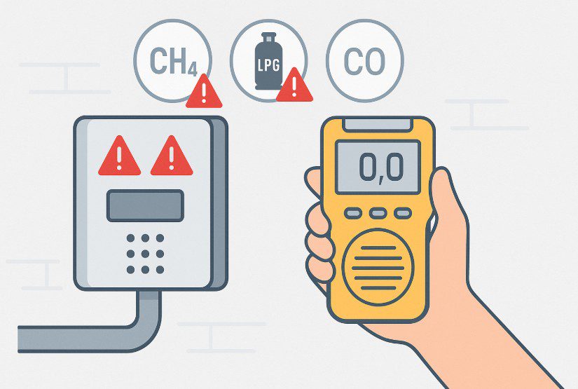
Leak Detection Systems
Solenoid valves connect to gas detectors, triggering automatic shutdown at 5% LEL (Lower Explosion Limit). These protective measures prevent accidents with 90% effectiveness. Natural gas, propane, and LPG detection systems feature 85dB alarms and LED warning indicators.
Pressure Relief Components
Standard applications require strict pressure control between 200 and 500 mbar. Pressure relief mechanisms guard downstream equipment through automatic activation during abnormal pressure events.
Fail-Safe Operations
Electronic controls integrate fail-safe modes into solenoid systems. Power interruptions trigger automatic valve movement to safe positions. Two fail-safe designs protect system integrity:
- Spring-return systems for immediate response
- Battery-backup systems for controlled closure preventing pressure waves
Manual reset requirements after power restoration prevent automatic flow resumption. This safety measure ensures proper system evaluation before operation resumes.
Installation Requirements and Standards
Gas solenoid valve installation demands precise adherence to manufacturer specifications and safety standards. Proper installation practices ensure reliable performance and hazard prevention in gas control systems.
Mounting Position Guidelines
Valve performance relies heavily on mounting orientation. Gas solenoid valves need vertical or horizontal installation with the coil positioned at the highest point.
The installation location requires a horizontal pipe section showing minimal vibration. Flow direction arrows on the valve body must align exactly with system flow.
Electrical Connection Safety
Safe power connections require careful attention to detail. AC power systems need correct wiring to live, neutral, and earth terminals. Wiring materials must handle ambient temperatures reaching 220°F.
The actuator power supply needs fused isolation switch protection against electrical faults. Junction box installation demands precise cover plate positioning with proper sealing gaskets.
Gas Line Compatibility
Gas line preparation plays a vital role in system longevity. Upstream gas filters shield valves from debris damage while extending maintenance intervals. Pipeline systems need thorough purging before valve installation to protect diaphragm components.
System reliability improves through bypass connections for detection devices and sensors. Valve selection must match gas type specifications listed on product labels.
Common Gas Solenoid Applications
Gas solenoid valves play essential roles across multiple industries. Each sector demands specific valve configurations and safety features for automated gas flow control and operational safety.
Gas Supply Systems
Regulating and controlling natural gas flow.
Water Treatment
Purification of drinking water and wastewater management.
Fire Safety Systems
Automatic shut-off in case of leaks.
HVAC Systems
Climate control and heating applications.
Industrial Process Control
Manufacturing facilities depend on gas solenoid valves for pneumatic machinery operation and production process control. These valves handle air and non-aggressive gases at pressures between 200 and 500 mbar.
Automated production lines benefit from these components through precise gas flow regulation, maintaining consistent product quality.
Residential Gas Systems
Gas solenoid valves serve critical safety functions in household appliances. Furnace systems rely on these devices to control pilot light gas flow. Gas-powered clothes dryers incorporate solenoid valves to prevent fires and gas-related incidents.
Modern residential systems emphasize automatic safety features, stopping gas supply during power loss or system malfunctions.
Commercial Kitchen Equipment
Commercial kitchen operations require gas solenoid valves for several applications:
- Gas ovens: Natural gas flow management at precise rates and temperatures
- Steam cookers: Pressure and steam regulation through monitoring systems
- Fryers: Oil flow control with temperature maintenance
- Dishwashers: Hot water and steam circulation through multiple valves
Safety protocols guide valve operation, incorporating emergency shutdown systems and leak detection capabilities. Gas detection units monitor potential leaks, triggering automatic power shutdown through relay systems when necessary. This combination of safety and control features maintains efficient operation while upholding strict safety requirements.
Choosing the Right Solenoid Valve
Selecting the correct solenoid valve depends on several factors:
Voltage Requirements
Available in 12V, 24V DC, or 230V AC versions.
Operating Pressure
Should match the system’s pressure needs.
Material Compatibility
Ensuring compatibility with the gas type and environmental conditions.
Conclusion
Gas solenoid valves serve as fundamental components in modern gas control systems. Their electromagnetic principles deliver precise flow control while upholding essential safety standards.
The choice between direct-acting and pilot-operated designs provides solutions for diverse pressure needs and response requirements.
Safety features form the core strength of these devices. Emergency shutdowns, leak detection systems, and fail-safe operations prevent accidents with 90% effectiveness.
Manufacturing processes benefit from reliable control capabilities, while residential appliances depend on these valves for safe operation.
Quality solenoid valve selection proves essential for gas system safety and efficiency. Manufacturer guidelines direct proper installation practices, supported by systematic maintenance programs.
The gas control industry continues developing enhanced valve technologies. Safety mechanisms and control features adapt to modern automation requirements.
Knowledge of valve operations, configurations, and applications guides users toward appropriate system implementation choices.
Frequently Asked Questions about Gas Solenoid Valve
A gas solenoid valve is designed to control the flow of gas in various systems. It uses electromagnetic force to open or close a valve, allowing or stopping gas flow as needed in applications ranging from industrial processes to residential appliances.
When an electric current passes through the valve’s coil, it creates a magnetic field that moves a plunger. This movement either opens or closes the valve, controlling gas flow. The process is quick, typically taking between 5 to 150 milliseconds, depending on the valve type.
The main types include normally closed valves (which block flow when de-energized), normally open valves (which allow flow when de-energized), and bi-stable valves (which maintain their position without continuous power). There are also direct-acting and pilot-operated valves, each suited for different applications.
Gas solenoid valve systems often include emergency shutdown mechanisms, leak detection systems, pressure relief components, and fail-safe operations. These features help prevent accidents by automatically shutting off gas flow in case of leaks, power failures, or other emergencies.
Gas solenoid valves are widely used in industrial process control, residential gas systems, and commercial kitchen equipment. They play crucial roles in manufacturing facilities, household appliances like furnaces and dryers, and various commercial cooking appliances such as ovens, fryers, and steam cookers.
A normally closed valve stays shut without power and opens when energised, commonly used for safety shut-off. A normally open valve remains open without power and closes when energised, suitable for systems requiring continuous gas flow.
A gas solenoid valve uses an electromagnetic coil to control gas flow. When powered, the coil generates a magnetic field that moves a plunger to open or close the valve. When power is removed, a spring returns it to default position.
Failure may result from coil burnout, voltage instability, dirt contamination, diaphragm damage, corrosion, or incorrect pressure selection. Poor installation and lack of maintenance also contribute to reduced performance and shortened valve lifespan.
Choose based on gas type, operating pressure, flow rate, pipe size, voltage, temperature range, and compliance standards. Also determine whether normally open or normally closed configuration is required for proper fail-safe system design.